Precision X-Ray Measurement
Because frequency control with temperature variations is directly related to quartz orientation angle control, all AT crystals produced at Colorado Crystal Corporation are accurately measured and catalogued into tight angle groups. High technology equipment and processing techniques allow CCC to accurately X-ray and/or angle correct singly rotated crystal cuts and the more difficult doubly rotated crystal cuts which include among others the SC and IT cut. Engineering modifications have been made in the double diffraction x-ray systems to obtain a much higher order of resolution, achieving a repeatability of a fraction of a minute. In addition, we utilize two different EFG x-ray systems.
Superior Lapping Equipment
Colorado Crystal Corporation’s lapping equipment was engineered to achieve the finest in crystal performance. Its custom design allows for intermediate lapping, finish lapping and the polishing of crystal surfaces… with special attention given to uniform surface finish and parallelism, two of the most important factors affecting the “Q” and other motional parameters of the crystal resonator.
Cleaning and Plating Techniques
After lapping, all crystals produced at Colorado Crystal Corporation are selectively etched to preplate frequencies and meticulously cleaned to ensure great crystal performance. Various precious metals are used to obtain the maximum performance required by a customer’s specifications. Colorado Crystal Corporation’s metal deposition equipment has been specially engineered to obtain superior oil-free vacuums through cryogenic systems and thus greater purity of plating material; its unique layout design ensures uniform metal deposition.
Sophisticated Testing Capabilities
For the difficult task of measuring quartz resonators, Colorado Crystal Corporation utilizes some of the latest and most sophisticated test equipment in the crystal industry. Automatic data acquisition systems are employed in several test areas to simultaneously read and record highly accurate data on the quartz resonators. This data can be exchanged with other computers or stored for future use. Colorado Crystal Corporation’s specialized test equipment can be used in many configurations and be interfaced to our computer for ultra-precise testing. For extremely accurate and reliable testing our customers can rely on our testing capabilities to meet the exacting demands of today’s technology.
Hermetic Sealing of Quartz Crystal Packages
Colorado Crystal Corporation hermetically seals quartz crystals primarily using Coldweld packages.
![]()
- Coldweld packages – a sealing die compresses the base flange and cover flange under high pressure. The two flanges are fused together creating an extremely good hermetic seal. This sealing process is inherently very clean. Coldweld packages come in a wide variety of sizes and configurations and are suitable for a wide range of demanding applications.
- Glass package (currently not available from CCC) – a metal ring sits between the glass base and the glass cover. The metal ring is heated by induction through a RF generator. When the metal ring gets hot enough, the glasses melt together making the hermetic seal. Limited sizes are available.
- Resistance weld packages (currently not available from CCC) – a sealing die holds the base flange and cover flange together under relativity light pressure. An electrical charge is passed through the flange area melting the two flanges together.
- Solder seal (currently not available from CCC) – Most bases have a solder filled moat. The solder seal cover normally has a small hole near the top. The cover sits in the moat while the two pieces are heated. The base and cover are sealed together when the solder melts. The hole in the cover is then soldered closed completing the hermetic seal. Soldering flux is normally used in this operation.
- Surface Mount Devices (SMD) packages are available through our parent company.
General Quartz Crystal Terminology
- activity dip – A decrease in the activity (higher R1) associated with a change in temperature. This is normally related to another mode vibrating at the same time of the desired mode over a short temperature range.
- aging – aging of a quartz crystal is a general term usually applied to any change in electrical parameters (usually frequency) of a crystal unit taking place over a period of time. This rate of change of frequency is normally exponentially decreasing in character but can also be linear. The change is at its fastest rate during the first days of dynamic operation. There are many interrelated factors in the aging of a quartz crystal: leakage of seals, internal contamination, out-gassing of materials, stress, overdriving and many other small effects. Circuit changes in the oscillator can also shift the resonate frequency of the crystal. Since the effects of aging can not be easily determined by incoming inspection or short dynamic usage, it is imperative that, if aging is a major concern in design, the following suggestions should be considered:
*Operation of a crystal unit should be kept at the lowest ambient temperature possible. Crystal drive levels should be kept at a minimum.
*Dynamically age the crystal in its oscillator circuit, prior to final adjustments.
- allan variance – a method of describing the short term stability of oscillators in the time domain.
- bulk crystal losses – Bulk crystal losses are performance characteristics resulting from physical phenomena of quartz and are the sum of acoustic loading, molecular friction, and power transmitted to the mounting or holder. These vary with the mass, mode of resonance and frequency range of the device. Bulk loss is equated in the motional arm value of R1.
- capacitance ratio – the ratio of Co/C1 (static capacitance / motional capacitance).
- coupled mode – an unwanted mode that mechanically or electrically couples to the desired mode at some temperature. This usually causes an activity dip.
- C1 – (or motional capacitance, Cm). The capacitance that the resonator exhibits at series frequency. It is represented as the C1 element in the resonators equivalent circuit. The unit of measure is farads but this is commonly expressed in picoFarads (pF) 10-12 , femtoFarads (fF) 10-15 or attoFarads (aF) 10-18.
- Co (shunt capacitance or static capacitance). The electrostatic capacitance at the pins of a resonator which includes the electrodes and holder. This is not a piezoelectric property. The unit of measure is farads but this is commonly expressed in picoFarads (pF) 10-12.
- drive level – the amount of power dissipated or the amount of current through the crystal in a given operating circuit. Drive level is usually expressed in microwatts or in milliamps. Excessive drive level can result in possible fracture of the quartz resonator or excessive long-term frequency drift or other erratic behavior.
- DLD (drive level dependency) – drive sensitivity – how an electrical parameter (usually resistance, sometimes frequency) of a resonator changes as the drive level is varied.
- equivalent circuit of a quartz resonator – The series branch (motional arm) contains the piezoelectric properties of the crystal as they appear to the external circuit while vibrating at its resonant frequency. L1 or Lm (motional inductance) is associated with the mass of the crystal. C1 or Cm (motional capacitance) is associated with the elasticity of the crystal and R1 or Rm is the terminal resistance of the quartz resonator. Co represents the static capacitance of the unit. See Figure 1.
- frequency calibration – (Frequency calibration or tolerance) is the amount of frequency deviation from the desired operating frequency usually at a specific temperature. Accuracy requirements for frequency tolerances are typically expressed in percentage (±.0050%, ±.0020%, ±.0010%, ±.0005%, ±.00015% etc) or in parts per million ( ± 50, ± 20, ± 10, ± 5 PPM, ± 1.5 PPM etc).
- g-sensitivity – acceleration sensitivity – 2g – 2g tipover – frequency change due to acceleration or gravity changes. Can be specified as a vector sum (gamma) or on any individual axis as frequency change per g.
- IT cut – a doubly rotated cut whose Phi ( f ) angle is 19.1066O and whose Theta ( q ) angle will vary but for some designs it may be ~ 34.25O.
- L1 (motional inductance) – The inductance that the resonator exhibits at series frequency. It is represented as the L1 element in the resonators equivalent circuit. The unit of measure is henrys and sometimes expressed in milliHenrys (mHy) 10-3.
- Piezoelectricity – “pressure electricity”. Electrical polarization is produced during an applied mechanical strain.
- pullability – the amount of frequency shift that occurs when changing the load capacitor (CL) (or inductor) on the crystal.
- R1 (resistance) – (series resistance, Rs), (equivalent series resistance, ESR) – Equivalent resistance is the value of impedance the crystal exhibits in the operating resonant circuit. THE HIGHER THE RESISTANCE, THE GREATER THE ENERGY LOSS OF THE RESONATOR; THUS, MORE DRIVE OR POWER IS REQUIRED TO EXCITE THE RESONATOR. Equivalent resistance is different for each type of crystal cut and operating frequency. The unit of measure is ohms.
- perturbations (usually frequency, sometimes resistance) – associated with an activity dip. Usually expressed as the maximum allowable frequency deviation from a (polynomial) least squares curve fit.
- phase noise – a method of describing noise in the frequency domain.
- Q (quality factor) 2p * energy stored during a cycle / energy lost during a cycle. The higher the Q, the higher the frequency stability and accuracy capability of a resonator.
- retrace – usually means the difference in frequency (before and after) due to turning a warmed up oscillator (or oven) off for an amount of time then turning it back on.
- SC cut – a stress compensated doubly rotated cut whose Phi ( f ) angle is ~ 21.93O and whose Theta ( q ) angle will vary will vary but for some designs it may be ~ 34.25O. This cut and other doubly rotated crystal cuts may have a strong undesired B-mode response approximately 10 % above the desired C-mode frequency.
- spurious modes (spur) – an undesired mode of vibration usually related to one of the inharmonic modes.
- TC (temperature coefficient) – is the frequency stability or frequency deviation with temperature change. Normally TC is expressed in parts per million (PPM) change or percentage of frequency over the operating temperature range referenced to the crystal frequency measured at a specified temperature. TC can also be expressed as turning point ranges, slope, and other ways of specifying frequency change over temperature.
- thermal hysteresis – usually means the frequency difference (at the same temperature) while cycling the temperature and monitoring the frequency during the temperature cycling.
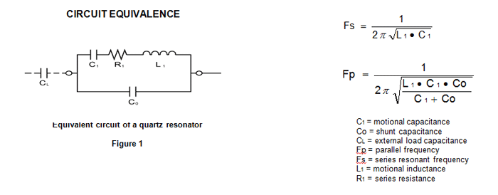
In Figure 1, R1 represents the terminal resistance, C1 represents the motional capacitance, L1 represents the motional inductance, and Co represents the static capacitance across the terminals. The series L1 C1 R1 branch represents the piezoelectric properties of the crystal as they appear to the external circuit when the crystal is vibrating at its resonant frequency. The motional arm inductance is associated with the mass of the crystal and the motional capacitance is associated with the elasticity of the crystal. The power, or heat, in the quartz resonator must be dissipated by the enclosure. Excessive power greatly reduces overall stability. External capacitances from crystal to oscillator can affect frequency correlation.
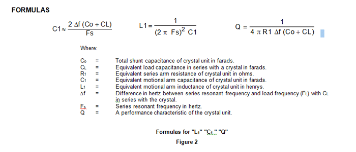
Many crystal manufacturers will supply values for L1, C1, Q, R1, Co, and Fs. With the proper values inserted in the illustrated formulas, the pull range (load frequency FL) can be calculated for any value of CL in series with the crystal. An understanding of these formulas will aid in circuit design. Precision crystals require that all referenced parameters be stated.
A crystal unit is normally intended for use only within a very narrow frequency range, centered at a specified nominal frequency. When a crystal is used as a passive element and the frequency is swept from a lower to a higher frequency the minimum impedance from Fs (maximum transmission) to Fp (minimum transmission) will change from a very few ohms to megOhms. Although a crystal will operate at any frequency between Fs and Fp, depending upon circuit conditions, it is desirable to operate close to the Fs frequency as frequency stability is less affected by external circuit capacity changes.
A convenient method of adjusting a crystal to a specified frequency is to connect a variable load capacitor (CL) in series with the crystal unit. The amount of pullability (frequency tuning) is controlled by the C1 and Co values of the crystal and the value and range of the CL capacitor. Series inductors may be employed to increase the pull range of crystals.
Proper selection of the type of crystal will also assure improved stability. For the same frequency and crystal cut, the mass of quartz in a 3rd overtone crystal is three times as great as that in a fundamental, while the mass of a 5th overtone is five times as great as that of a fundamental. The increase in mass directly resulting from selection of 3rd or 5th modes of oscillation also improves stability but will decrease C1 therefore decreasing pullability.
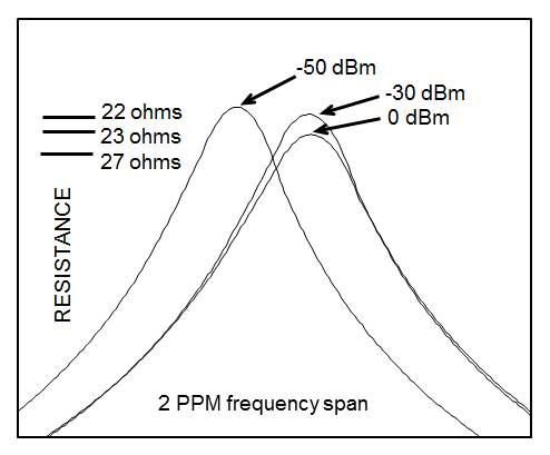
Figure 3
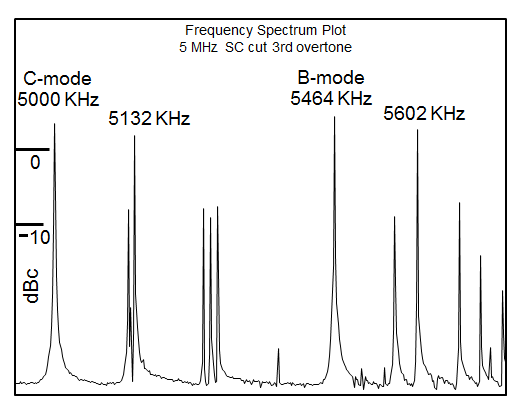
Figure 4
Figure 3 shows a crystal that was tested for Drive Level Dependency (DLD). In this example there were three frequency sweeps with each frequency sweep being at a different drive level. DLD can also be tested using an amplitude sweep. Within reasonable drive limits for a given design, there should not be excessive resistance or frequency shifts.
Figure 4 is a plot showing the frequency response for a particular SC cut design. Note that the B-mode frequency is about 9.6 percent above the C-mode frequency. The inharmonic overtone modes (spurious modes) are also shown for each mode.
TEMPERATURE COEFFICIENT CHARACTERISTICS
Quartz crystals may be designed to operate over wide or narrow temperature ranges. Temperature/frequency characteristics can be altered to give optimum stabilities over any specified range. The TC (temperature coefficient) is largely controlled by proper angle orientation during X-ray measurement. TC can be expressed in many ways including plus or minus parts per million (PPM) over a given temperature range, UTP (Upper Turning Point) range, LTP (Lower Turning Point) range, Slope, delta PPM between turning points and other methods or combinations.
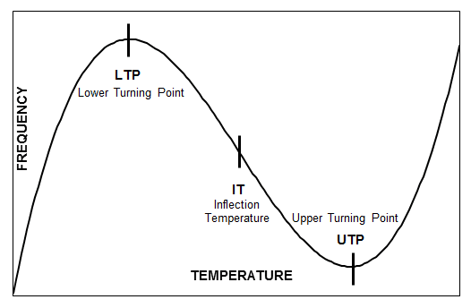
Figure 5
Figure 5 is a TC curve showing turning points and an inflection temperature. A turning point that is lower in temperature than the inflection temperature is called the lower turning (LTP) and a turning point that is higher in temperature than the inflection temperature is called the upper turning point (UTP). The LTP and UTP are symmetrical around the inflection temperature. Crystal cuts whose frequency-temperature characteristics generally follow a 3rd order polynomial fit will have an inflection temperature but not necessarily turning points. Negative curves will have inflection temperatures but no turning points. Positive curves will have inflection temperatures and turning points. Setting the first derivative of the 3rd order polynomial to zero then calculating for ‘x’ will solve for the turning points while setting the second derivative of the 3rd order polynomial to zero then calculating for ‘x’ will solve for the inflection temperature.
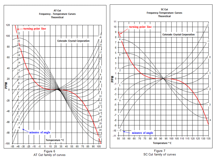
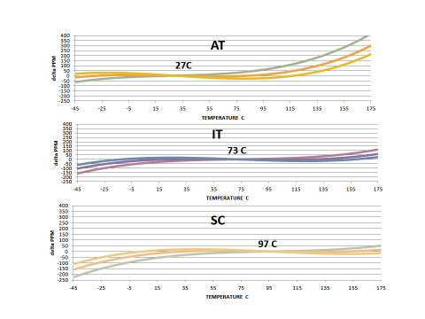
Figure 10
General family of curves for the AT, IT, and SC cuts showing the approximate Inflection Temperatures
Applications
There are many applications utilizing piezoelectric quartz with more being developed all the time.
- OSCILLATORS
- FILTERS
- DESCRIMINATORS
- TRANSDUCERS
- SENSORS
Some Common End Use Applications
- NAVIGATION SYSTEMS
- SATELLITE COMMUNICATIONS
- RADAR
- TELECOMMUNICATIONS
- COMPUTERS
- SONAR
- ENVIRONMENTAL MONITORS
- ROBOTS
- AIRCRAFT COMMUNICATIONS
- MARINE COMMUNICATIONS
- CHEMICAL / BIO SENSORS
- AMATEUR RADIO
- POLICE AND FIRE RADIO
- CELLULAR TELEPHONE
- WILD LIFE TRACKING
- ATOMIC STANDARDS
- DISTANCE MEASURING EQUIPMENT
- Q SWITCHING ON LASERS
- WEAPONS SYSTEMS
- FREQUENCY COUNTERS
- SPECTRUM / NETWORK ANALYZERS
- VIDEO GAMES
- WATCHES AND CLOCKS
- MEDICAL INSTRUMENTATION
- ENGINE GOVERNORS
- AUTOMOTIVE IGNITION SYSTEMS
- HEART PACEMAKERS
- SPACE CRAFT COMMUNICATIONS
- OIL and GAS TEMPERATURE and PRESSURE SENSORS